
Fully Filled Polyethylene Unit Twin Cable with Moisture Barrier Sheath
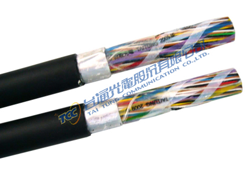
CP-FS-FF-LAP
The high quality insulated cable used subscribers distribution. Featuring: The cable is insulated full color coding with an extruded foam-skin insulating high-density polyethylene compound in the air space to water resistant filling compound.
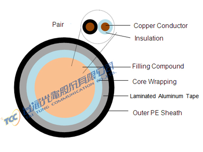
- Conductor: Solid annealed copper wire in size 0.4, 0.5, 0.63mm.
- Insulation: Foam-skin Polyethylene
- Twinning: Two insulated conductor are twisted into a pair.
- Cable Formation:
Twisted pairs are assembled to form a substantially cylindrical group of 25 pairs (called unit). When desired for lay-up
reasons, the units are divided into two or more sub-units.
If the cable size up to 50 pair and including 50 pairs,
Cable will consist of 10 pairs stranded together to form a compact bunch, which can be further divided into two sub-units of 5 pairs.
If the cable size of 100 pairs and above
Single Unit (25 pairs)
A single unit will consist of 25 pairs stranded together to form a compact bunch.
Double Unit (50 pairs)
Two singe units of 25 pairs will be stranded together to form a double unit.
Quadruple Units (100 pairs)
Four single units of 25 pairs will be stranded together to form a quadruple unit.
Spare Pair Unit
A spare pair unit will be incorporated in 300 pair and larger pair cables.
The spare pair unit will be laid up in an outer interstice of the cable.
- Unit identification tape
- Filling Compound
- Core Wrapping
- Cable identification tape
- Moisture Barrier
- Ripcord
- Sheath: extruded black polyethylene
- Flame Retardant Sheath
Electrical Characteristics at 20℃
|
Item\Conductor Diameter |
0.4 |
0.5 |
0.63 |
||
|
Conductor Resistance |
Maximum individual value for 99%of cases |
143 |
91 |
58 |
|
|
Max value |
150 |
96 |
60 |
||
|
Min. Insulation Resistance(MΩ/km) |
Min 1,500 500V d.c/1min. |
||||
|
Spark test of sheath |
KV |
6 |
|||
|
Mutual Capacitance |
Maximum Average Value |
Average value: ≦56 nF/km |
|||
|
Maximum individual value for 99% of cases |
Average value: ≦64 nF/km |
||||
|
Capacitance Unbalance (at 1kHz) |
Max. individual value for adjacent pairs(Pf/500m) |
275 |
|||
|
Far-End Crosstalk Loss (at 150kHz) |
RMS |
Min. 67.8dB/km |
|||
|
Any pair combination |
Min.57.8 dB/km |
||||
|
Near-End Crosstalk Loss (at 772kHz) |
Unit Pair Size |
M-S dB |
|||
|
Within Unit |
13 or less |
Min.56 |
|||
|
25 |
Min.60 |
||||
|
Between Unit |
Adjacent 13 or less |
Min.65 |
|||
|
Adjacent 25 |
Min.66 |
||||
|
Non-Adjacent |
Min.81 |
||||
|
Attenuation Nominal (dB/km) |
40 kHz |
8.5 |
5.9 |
4.1 |
|
|
120 kHz |
11.3 |
7.7 |
5.5 |
||
|
150 kHz |
11.8 |
7.9 |
5.9 |
||
|
772 kHz |
21.3 |
18.4 |
13.1 |
||
|
Dielectric Strength |
Conductor / Conductor |
A.C.360/2(R.M.S); D.C.550/1 |
|||
|
Conductor / Ground |
A.C. 1000/2(R.M.S); D.C.1500/1 |
||||